Sensor Lab

Sensor Lab is the project that a couple of friends and I, set as the first activity for our start-up LOTUS, and I’d been developed it in my leisure time for almost a year. It’s a simple and low-cost, but innovative and useful microcontroller device, which can drive and measure plenty of sensors. The project consists of two parts, the hardware and the software.
Consider the list of sensors below supported by Sensor Lab:
- Any analog sensors with linear output range up to 4.096V
- DS1620 – digital I2C temperature sensor
- HIH-400 – linear humidity sensor
- K-Type thermocouple
- LM35 – analog temperature sensor (0˚C to 150˚C)
- LM75 – digital I2C temperature sensor
- LM335 – analog precision temperature sensor
- Any load-cells – weight sensor
- Industrial NPN and PNP proximity sensors
- PT100 – two, three, and four wire connection mode
- Any resistive sensors – with the input resistor connected to +5V
- Any resistive sensors – two and four wire connection mode
- SMT160 – digital PWM temperature sensor
- TSL230 – digital light sensor
- TSL250 – digital light sensor
- UGN3503UA – linear hall-effect sensor
- Wheatstone bridges
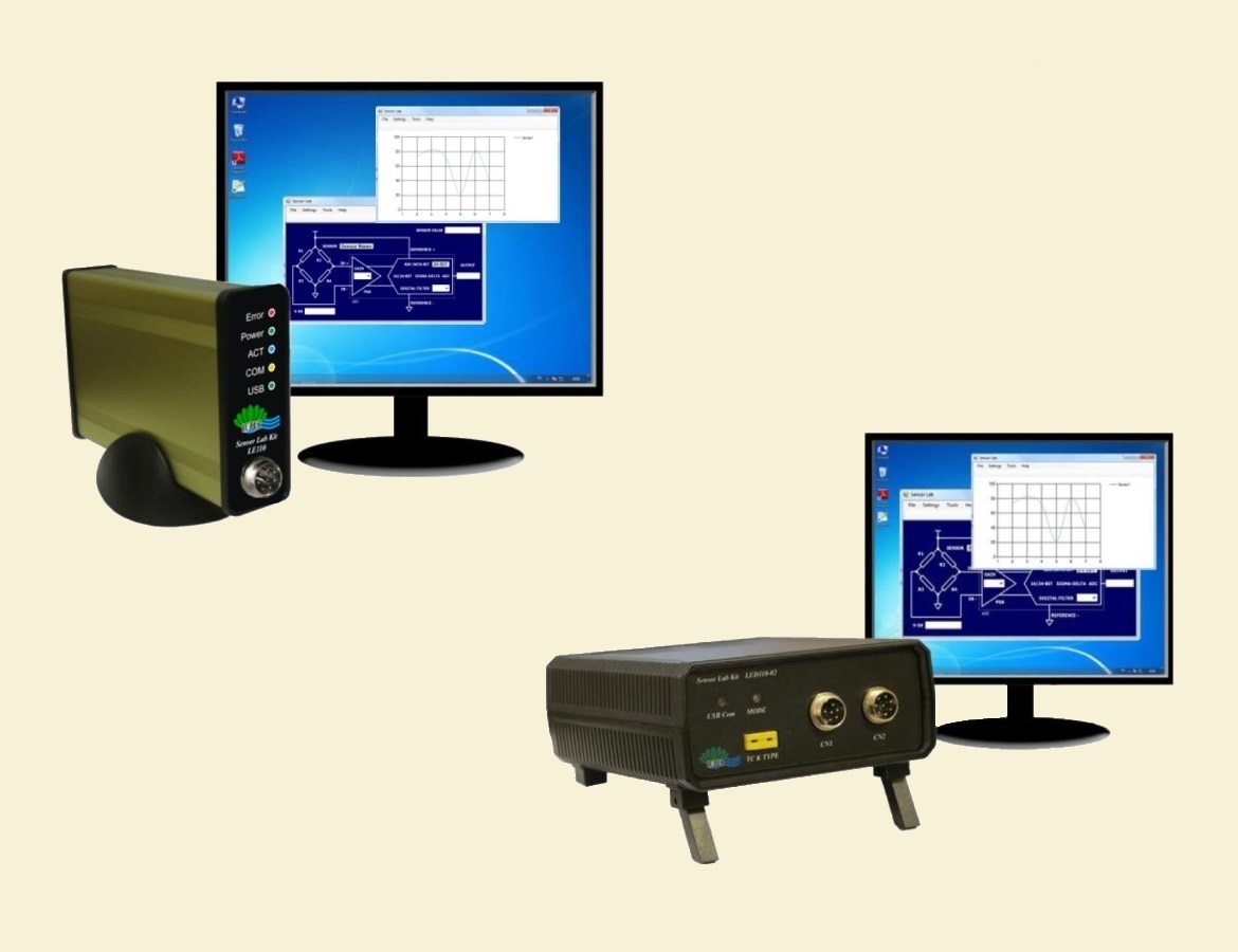
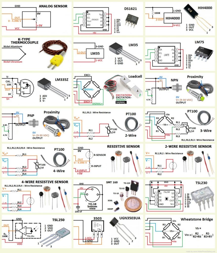
The hardware is connected to a computer running SensorLab software to send measured data to and get settings and command from the software. The microcontroller used in this device is ATmega16A, connected to AD7190 – a 24-bit Sigma-Delta ADC from Analog Device. There is also a MAX6675 connected to the MCU on the SPI, which is a 0˚C to 1024˚C K-Type Thermocouple to digital converter. The FT232 – USB to Serial – chip is used to connect the device to the computer. The device has three input connectors CN1, CN2, and CN3 for connecting sensors. CN1 is connected to the AD7190 ADC and provides a very accurate measurement. CN2 is connected to the ATmega16A – digital I/Os and analog inputs channel. Both CN1 and CN2 provide power pins in order to supply connected sensors. CN3 is connected to the MAX6675, and a K-Type thermocouple up to 1023˚C can be connected to it. The connectors pin-out and sensors wiring map are available on the SensorLab software while the user is choosing the sensor, and are as follows:

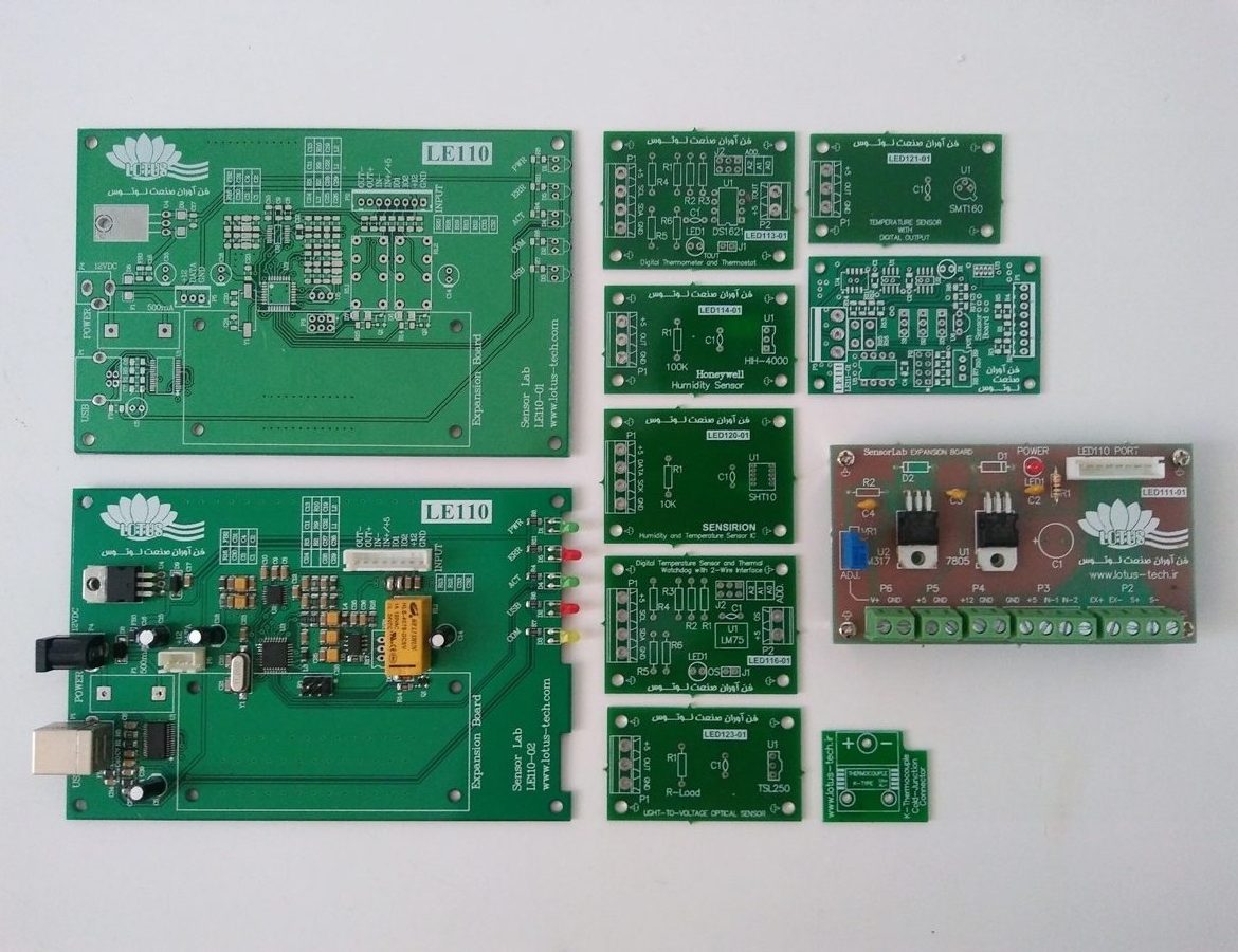
The PCB has been developed in several versions. Below is the latest one.

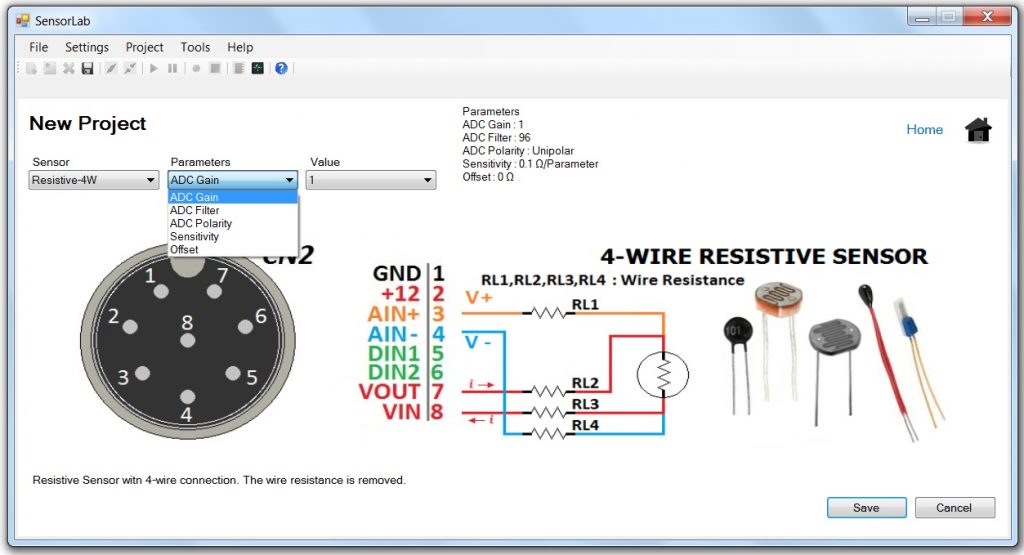
The software has been developed with .NET Framework and C#. It configures the device according to selected sensor, receives measured data from the device, and monitors information, after calculating, on the block diagram of the selected sensors. User can make a new project and choose a sensor from the list, or open an already made project. There are several parameters for each sensor, which users can change. The software will warm the user in case of any error in set parameters. After making (and saving) or opening the project, the screen of the selected sensor appears, monitoring set and measured value of the sensor. The user can stop or start the measurement and record measured data on the computer. They also can set an interval for recording. Recorded files can be viewed with the Graph tool available on the Home window or Tools menu. To achieve more accuracy, the device can be calibrated by several commands with a serial terminal through the USB port, setting the actual value of the reference voltage, VCC, and the internal series resistor, measured by precision equipment. Block diagram screens of sensors and some of the software screens are as follows:


PROJECT INFO.
- CLIENT: LOTUS Tech
- DATE RELEASED: 2014
- MY TASKS: Entire the Project - HW, FW, and SW Development
- TAGS: AVR Microcontroller, ATmega16, AD7190, 24-bit ADC, Analog Device, MAX6675, C# .NET, RS-232, FT232RL, Analog Sensor, Digital Sensor, DS1620, I2C, HIH-4000, Humidity Sensor, K-Type Thermocouple, Temperature Sensor, LM35, LM335, LM75, Load-cell, NPN/PNP Proximity Sensor, PT100, SMT160, PWM, TSL230, TSL250, UGN3503UA Hall-effect Sensor, Wheatstone bridge