LIS3DSH Accelerometer
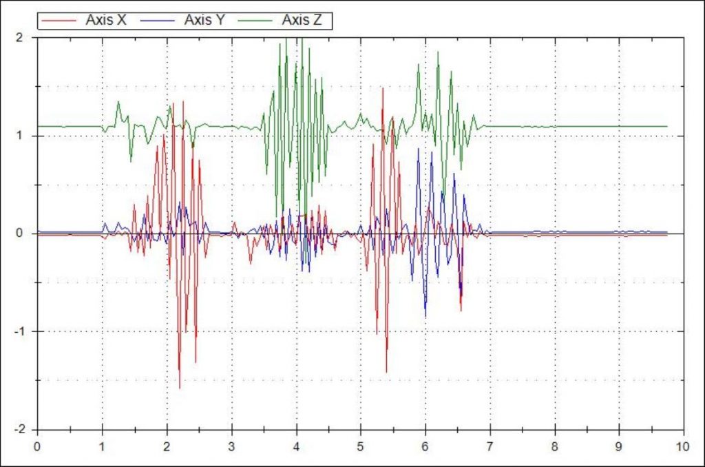
This is a 3-axis accelerometer sensor with analog outputs, using LIS3DSH digital MEMS sensor from STMicroelectronics, which connects to digitizer, in order to record seismic waves.
Device Specifications:
- Digital 16-bit 3 axis MEMS sensor
- Analog output ±5V (compatible with particular digitizer)
- Selectable axes (X, Y, Z single or together)
- Selectable bandwidth (800/400/200/50 Hz)
- Selectable full scale (2/4/6/8/16 G)
- Selectable output rate
- Fully software base calibration, configuration, and monitoring
- Dynamic range 96 dB (according to 16-bit ADC)
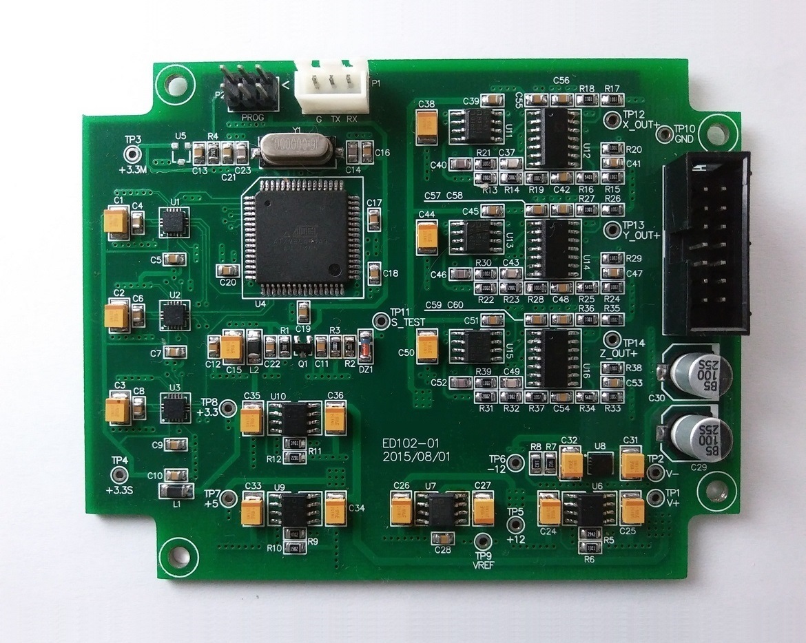
There are three MEMS sensors placed on the prototype hardware in order to compare various parts in indifferent conditions, such as initial error.
Some of the project requirements are as follows:
- Dynamic range over 85 dB
- Low production time through fast calibration procedure
- Allow change of the sensor full scale in the field without recalibration being required
- Maintain as low hardware cost as possible
- Maintain electrical and mechanical compatibility with existing recorders
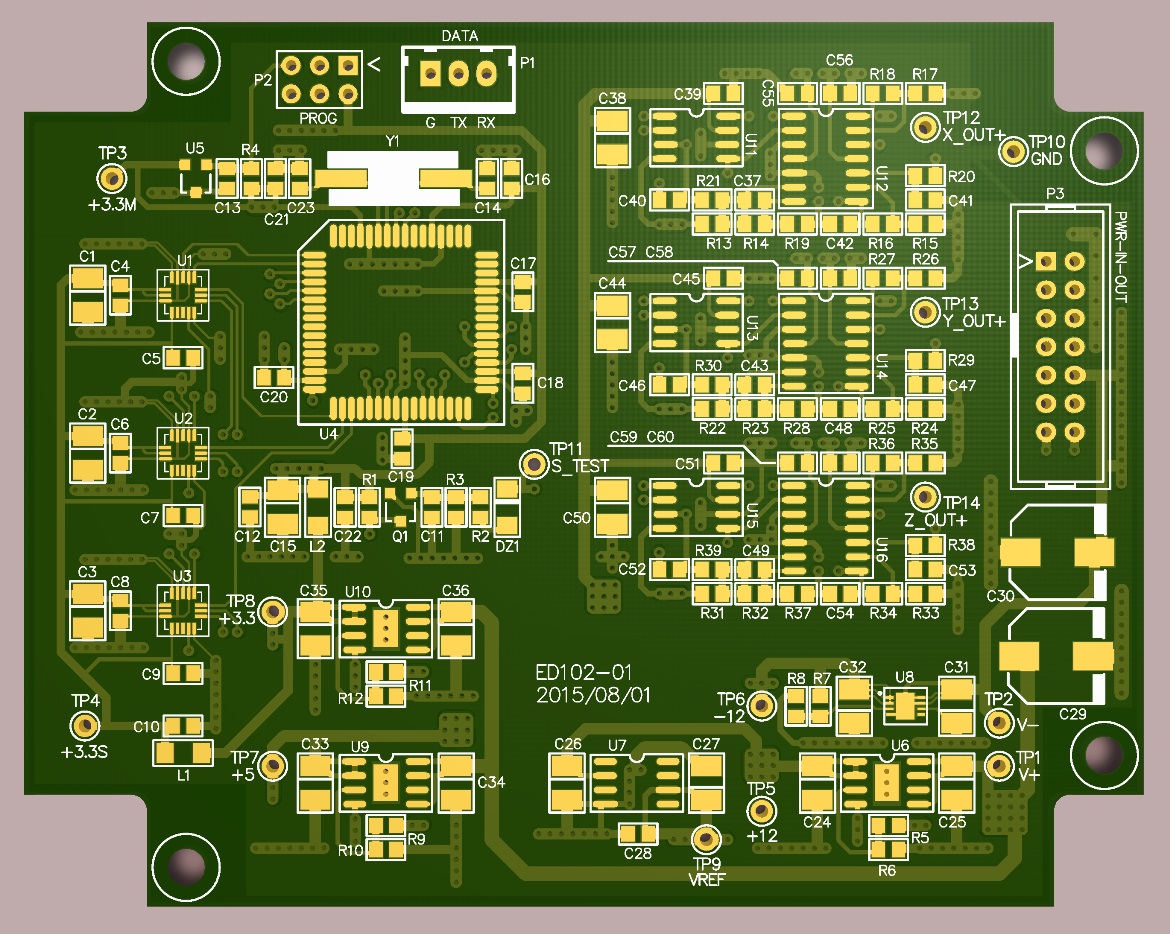
Device block diagram is shown below. In general, the microcontroller reads axes data from sensors via SPI, and then writes each axis data to its relevant DAC connected to another SPI. Each analog signals exited from DACs applies to a 2nd order low pass Butterworth filter with a gain of 2, and then appears on the output connector.

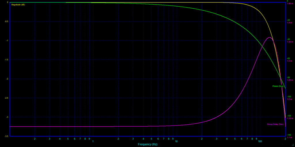
Using digital sensors and converting data to analog signals, makes it possible to configure sensor parameters by software. However, getting and sending data by a microcontroller can cause a phase shift on output signals, which is an undesirable consequence.
The filter used in this design is a 2nd order low pass Butterworth filter with a gain of 2, Sallen Key topology, pass band frequency of 1500Hz, and designed by Filter Solution 2009. Filter parameters, schematic, and response are as follows:


Calibration/configuration software has been developed by C# .NET communicating with the device via serial port and enables user to set following parameters, and also to monitor measured data.
- Sensors in use
- Axes in use
- Output data rate
- Bandwidth
- Device serial number
- Reference voltage calibration
- Axis offset calibration
- Axis Gain calibration

This project is done by two persons working on close to three months. Thanks to Mr. Saied Aghamohammadian, who got me to cooperate whit him on this project, helping with PCB layout, firmware development, and software development.
PROJECT INFO.
- CLIENT: Private
- DATE RELEASED: Jul 2015
- MY TASKS: PCB Layout, FW, and SW Development
- TAGS: LIS3DSH, MEMS, ST, Accelerometer, Earthquake, Seismic, AVR, ATxmega, C# .NET