
There is a lot of information about the STM32 family microcontrollers on the Internet as they are using widely all over the world. So I have only listed some of the features, which made me choose them as the main target in my projects. There are also a lot of evaluation and header boards for STM32 available on markets, and some of them like lovely Blue Pill are really useful and convenient.
- Variety range of microcontrollers
- More useful peripherals compared with other MCUs
- Fairly cheaper price than the other MCUs
- Be using by industries and many people
- So many information and resources
Getting started with STM32 is not a tough job at all considering available software and hardware tools. To have an easy start, we need the tools below:
- STM32CubeMX
- IAR EW for ARM (or any other IDE supporting STM32)
- Blue Pill – STM32F103C8 header board
- ST-LINK V2
STM32CubeMX is a very useful software tool from STMicroelectronics that provides a configuration environment for STM32 MCUs and their peripherals, and generates project files and configuration code for a number of IDEs such as ST, IAR SYSTEM, KEIL ARM, and EW, so that the generated project can be compiled in the corresponding IDE and programmed into the MCU.
IAR EW for ARM is an Integrated Development Environment – IDE – supporting a wide range of ARM microcontrollers such as STM32, which I am using it currently for STM32. Although the example in this article was done by it, you can use any other IDE supported by STM32CubeMX if you have worked with.
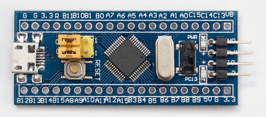
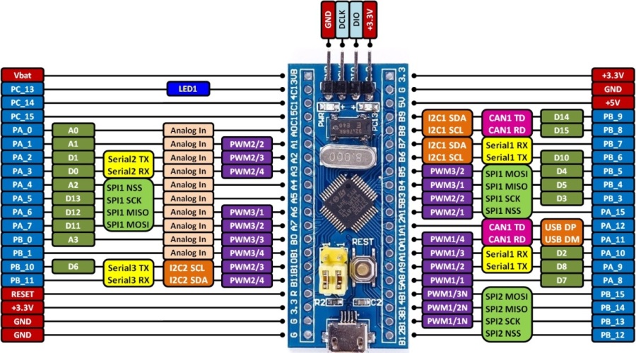
Blue Pill is a STM32F103C8 header board with a powerful MCU alongside with a really cheap price, which makes it worth having one. It will be the best choice for everyone who is going to start STM32. All the microcontroller’s pins are available on the pin headers. The SWD pins are separated on the board. The reset push button, boot select jumpers, 8MHz crystal, power LED, and one more LED connected to the GPIO, make it more comfortable. The mini USB connector is connected to the USB pins on the MCU and also powers the board. The 3.3V regulator on the board makes it possible to power from a 5V supply through the USB connector or the power pin headers. Consider the Blue Pill board, pin-out, and schematic as follows.

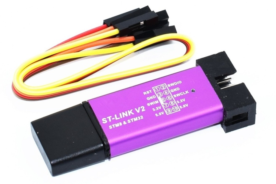
ST-LINK/V2 is an in-circuit debugger/programmer for STM8 and STM32. It supports JTAG and SWD for STM32, and SWIM for STM8. The original and Chinese type of this tool is shown below.

There is another copy model of ST-LINK/V2 which is so smaller and cheaper than the original one, and works as well. This model is shown below.
STM32 – Hello World
Now, it is time to go over the first project with STM32, to blink the green LED on the Blue Pill, connected to PC13 on the STM32F103C8T6.
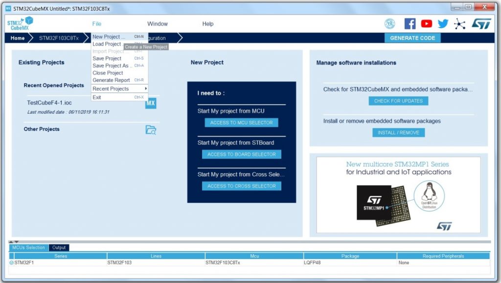
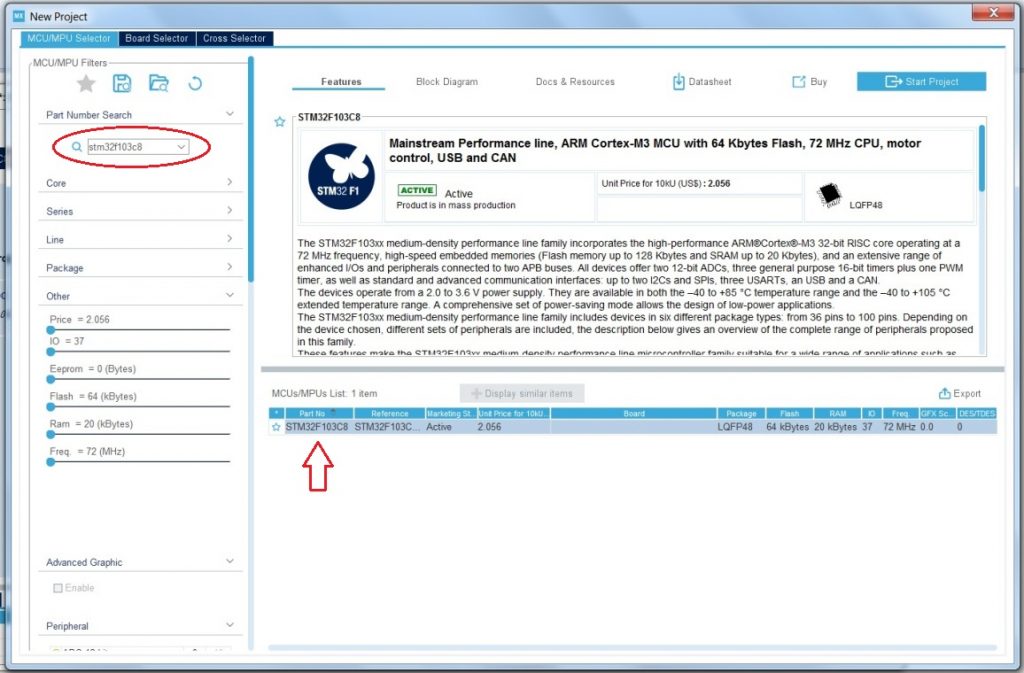
After installing STM32CubeMX and the IDE – IAR in this example, just run the STM32CubeMX and on the Home window, choose New Project from the File menu.
In the new project window, choose the MCU from the list below the window, or by writing STM32F103C8 in the search box. Then double click on the MCU name in the list below the window.
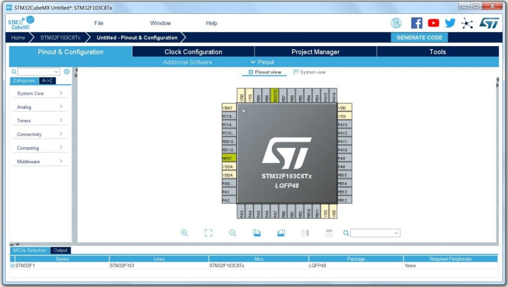
Then, the pin-out view of the selected chip will be shown in the main window. Here we can configure the peripherals we need for the project.
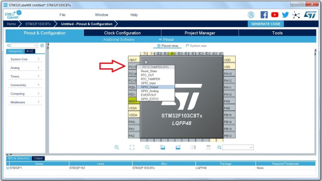
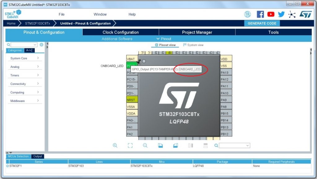
First of all, we need to set the PC13 as output as the onboard LED on the Blue Pill is connected to it. The PC13 pin is the 13th bit of the GPIOC and is shown in the picture below. Click on the pin and choose the GPIO_Output.
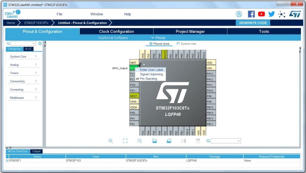
You also can define a name for this pin like ONBOARD_LED, so the name will be defined for it in generated code. To do this, right click on the pin and choose Enter User Label, and write ONBOARD_LED in the text box. This name is optional and you do not have to use a name, or you can choose another name.
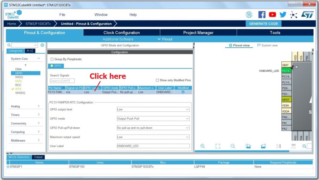
You can configure each GPIO pin with more details by clicking on System Core and then GPIO, in the left side menu. Then all GPIOs you changed in the previous level will be listed. By clicking on each one, its parameters will be shown above it.
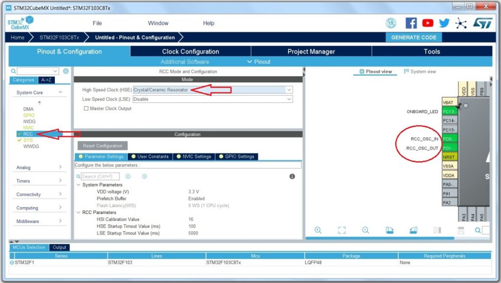
Now, we should configure the system clock. As there is an 8 MHz crystal connected to the MCU on the Blue Pill, we’d better to use HSE (High Speed External) oscillator as the system clock source. However, there are three more clock sources available on the STM32F103 family, consist of HSI (High Speed Internal – an 8 MHz internal RC oscillator), LSI (Low Speed Internal – 40 KHz internal RC oscillator), and LSE (Low Speed External – external 32.768 KHz crystal connected to the OSC32_IN and OSC32_OUT). On the left side menu, click on the System Core and then RCC. In mode section, select Crystal/Ceramic Resonator for High Speed Clock (HSE), so that RCC_OSC_IN and RCC_OSC_OUT will appear in the pin-out view. Be aware that only the clock source will be configured this time and we need to specify the system clock frequency as we will do it next.
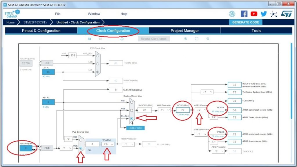
Click on the Clock Configuration tab on the top and change the parameters according to picture below. As you can see, the HSE is selected as the PLL clock source. The PLL multiplier value was set to 9, so the PLL output frequency (PLLCLK) equals 72MHz (8MHz * 9). Then, select PLLCLK in System Clock Mux as the SYSCLK. The HCLK will be 72MHz, which is the maximum clock available for it. The maximum value is written below the HCLK textbox in blue. If the selected clock is more than the maximum value, it will warn you by red color, and should be corrected. The maximum frequency for PCLK1 is 36MHz. So, with the 72MHz HCLK frequency, the APB1 Prescaler should be set to 2. Now we have the maximum clock frequency for all the peripherals from an external crystal.
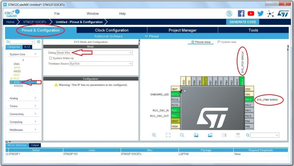
After configuring the system clock frequency, click the Pinout & Configuration on the top and then SYS under the System Core menu in the left side. Select Serial Wire in front of Debug, so that the SWD – program and debug – pins will be appear in the pin-out view.
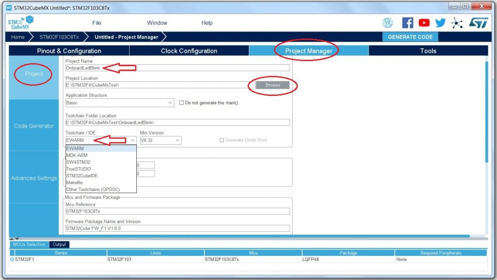
Now, the hardware configuration is done, and we go for configuration of the project and generating files. Click on the Project Manager tab on the top and in the Project section, write a name for your project under project name. As it is shown below, I chose OnboardLedBlink. Then select the location you want to save the project there by clicking on the Brows button. In the Toolchain/IDE, you should select the IDE you want ro the project code be generated for. I selected EWARM to tell STM32CubeMX to generate code for IAR, but you can select any other available options.
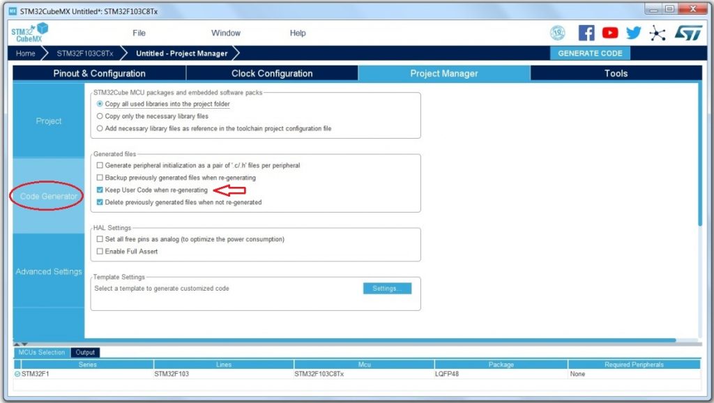
In the Code Generator section, there is no need to change any options. STM32CubeMX is flexible and it makes it possible that user open and change their already made project after adding their own code in the source files. To apply changes in the project without affecting user defined code, Keep User Code when re-generating, should be checked as follows, which is checked by default. Also user code should be written in particular parts specified in the generated project code.
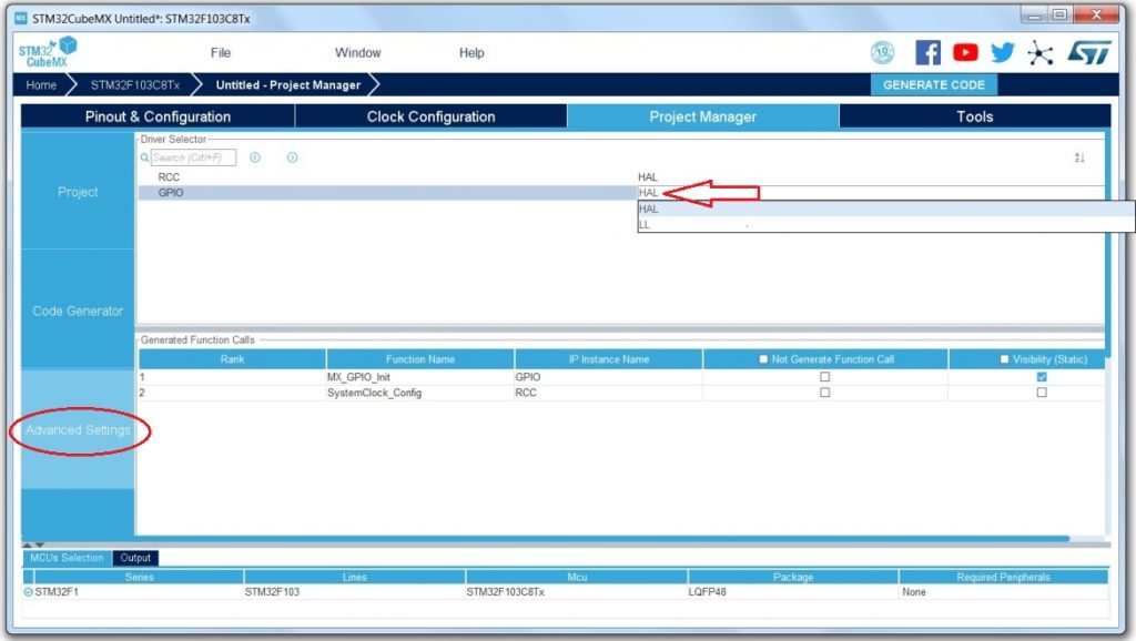
In the Advance Setting section, we can select the driver library for configured peripherals. HAL and LL are two library available for most peripherals. HAL is quite more high Level than the LL (Low Level), but more convenient and easier to use, while LL gives more efficiency and leads to a faster code using fewer function calls and instructions. Leave the settings here unchanged (HAL) as it does not matter in this example and even in many projects later.
At the end, click the Generate Code button on the top to generate the project files. The STM32CubeMX might need to some software packages while you are generating the project code. In that case, it warns you and you need to be connected to the Internet and update the repository. If everything is right, the project files will be generated and stored in the path you have specified in the project section and the code generation window will be shown as follows.
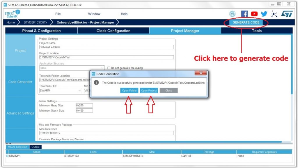
You can open the folder containing your project file, or open the project in the IDE the project was generated for. Here we choose Open Project, so that the IAR will be executed opening our OnboardLedBlink project.